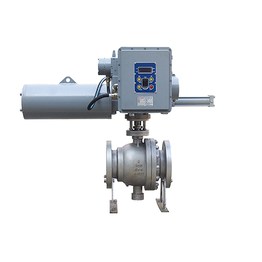
AT30/31 Series
-
Ambient Temperature
Normal: -20~70℃
Low: -40~70℃ -
Ingress Protection Level
IP66;IP67;IP68
-
Explosion-proof Level
Ex d IIC T4;Ex d IIB T4
-
Safety Integrity Level
SIL2/SIL3
AT30/31 Series
| ● Servo pump control design, high reliability, low energy consumption, low maintenance cost | ● Modular design, flexible combination of different specifications to meet load requirements |
| ● Intelligent electronic control, visual interface, rich functions, to meet various process requirements | ● Independent hand pump module for easy commissioning and emergency operation |
| ● Hydraulic power transmission, large output torque, high transmission efficiency, reliable over-torque protection | ● Flexible installation method, which can be installed as a whole or separately, adapting to complex site conditions |
| ● Spring storage fault reset power, wider ambient temperature adaptation range | ● Reliable protection and explosion-proof performance |
| ● Integrated and integrated design, self-contained power and oil source, small size, no external hydraulic piping required | ● Fully electrically isolated signal interface |
| ● A variety of power options, wide ambient temperature range | ● A variety of power options, wide ambient temperature range |
| ● Optional switch and adjustment, optional linear stroke and angular travel | ● Remote control jog, remote control long-distance and remote control analog adjustment function |
| ● High-speed fault reset function, which can realize fault full opening, fault full closing and fault keeping function | ● Full open hold, full hold, position hold function |
| ● Fault self-diagnosis function | ● Fully open and enhanced |
| ● Location and local long-distance function | ● PST partial stroke test function |
| ● Field installation verification positioning and parameter setting function | ● Fully open, fully closed and valve position feedback |
| ● Fault alarm and reset function |
|
● Power supply (optional): DC: 24V; 48V; 72V
AC (50/60Hz): 110VAC/1P; 220VAC/1P; 380VAC/3P; 400VAC/3P; 415VAC/3P |
● Control mode (optional): On/Off type modulate Type (including On/Off type function)
Control signal: dry contact or 24VDC 4-20mA or 20-4mA Status feedback: dry contact dry contact Valve position feedback: 4-20mA active 4-20mA active |
| ● Torque range (Rotary type): 75Nm~40,000Nm | ● Basic error: ≤0.2% ≤0.5% |
| ● Thrust range (Linear Type): 10KN-320KN | ● Repeatability: ≤0.2% ≤0.5% |
| ● Fault reset (optional): IP66; IP67; IP68 | ● Adjust dead zone: 0.2% 0.5% |
| ● Protection level (optional): IP66; IP67; IP68 | ● Action response time: ≤0.5s |
| ● Explosion-proof Level (optional): ExdIIBT4; ExdIICT4 | ● Ambient temperature (optional): -20 ° C to +70 ° C; -40 ° C to +70 ° C |
| ● Control accuracy (optional): 0.2 level 0.5 level | ● Electrical interface: NPT3/4(F)*2, NPT1(F), NPT1 1⁄4(F) |

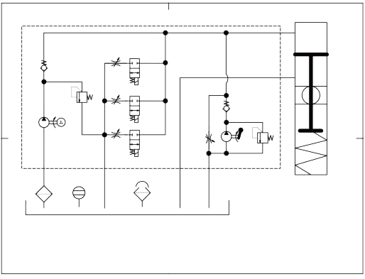
Hydraulic schematic
Electrical wiring diagram

NOTE-1
Figure 1 and Figure 2 above show wiring diagram of the mode knob in the REMOTE position. The local OPEN/CLOSE/CAL button is invalid. Figure 1 is the 24VDC using the actuator. Figure 2 shows the 24VDC outside the actuator.
NOTE-2
When the IN-STOP distal normally closed button is open (pressed), it is in LATCH mode. Press and hold OPEN or CLOSE to control the valve action.
NOTE-3
THREE mode when the IN-STOP distal normally closed button is closed (not pressed)
The THREE mode divides the OPEN and CLOSE action processes into three intervals, and each of the three sections sets the speed, which can play the role of mitigating impact and waterproof hammer.
The interval setting, the motion speed, and the stop time are all set in the user menu ten.
Click the OPEN button. The actuator will always run to the F/O state.
Pressing the CLOSE button will cause the actuator to run to the F/C state.
When the STOP button is pressed during operation, the actuator stops running.
NOTE-4
SEL switch for selecting digital control (DI) or analog control (AI)
In AI mode, the actuator inputs a 4-20 mA analog signal according to the Al terminal {corresponds to 0-100% of the stroke). Drive the valve to the appropriate position at the set speed.
In the Al mode. Press the remote STOP button or press the local STOP button or toggle the actuator to stop the action and issue a forced stop alarm message.
The opening feedback signal is 4-20 mA corresponding to 0-100% of the stroke.
NOTE-5
The EMG signal is a chain signal access terminal, which only works in the REMOTE state, and the EMG signal is a continuous signal. When the EMG signal is valid, the actuator performs valve opening or closing according to the set requirements, and is used as a chain control.
| AT | 3 | 0 | -01 | -M | E | -90° | -xxxx |
| Aero Electro-Hydraulic Actuator | Spring Fault Reset type |
0: Rotation 1: Linear |
Torque series Thrust series |
M: Modulate O: ON/OFF |
E: Explosion Protection W: Waterproof |
Rotation ° Stroke mm |
Special specifications |
| model |
Rated torque NM |
90° maximum running speed (S) | High speed fault reset (S) |
|||||||
| Power module | S1 | S2 | A | B | C | E | F | |||
| Maximum power consumption | 200W | 300W | 600W | 1.2KW | 3KW | 6KW | 8KW | |||
| AT30-00 | 75 | 4.0 | 3.0 | 2.0 | / | / | / | / | 1~2 | |
| AT30-01 | 125 | 16.8 | 12.5 | 7.0 | 4.2 | / | / | / | 1~2 | |
| AT30-02 | 300 | 27.3 | 20.2 | 11.0 | 6.4 | 2.9 | / | / | 2~3 | |
| AT30-03 | 630 | 48.4 | 35.6 | 19.0 | 10.7 | 4.5 | / | / | 2~3 | |
| AT30-04 | 1000 | / | 54.8 | 29.0 | 16.1 | 6.4 | / | / | 2~3 | |
| AT30-05 | 1500 | / | / | 41.0 | 22.5 | 8.7 | / | / | 2~3 | |
| AT30-06 | 3000 | / | / | 61.0 | 33.3 | 12.6 | / | / | 2~4 | |
| AT30-07 | 5000 | / | / | 101 | 54.8 | 20.3 | 10.5 | / | 2~4 | |
| AT30-08 | 8000 | / | / | 141 | 76.3 | 28.0 | 14.1 | / | 3~5 | |
| AT30-09 | 10000 | / | / | 201 | 109 | 39.6 | 19.8 | / | 3~6 | |
| AT30-10 | 15000 | / | / | 281 | 152 | 55.1 | 27.3 | 22 | 4~7 | |
| AT30-11 | 20000 | / | / | 401 | 216 | 78.2 | 38.6 | 30.6 | 5~8 | |
| AT30-12 | 25000 | / | / | / | 270 | 97.5 | 48.0 | 37.9 | 5~9 | |
| AT30-13 | 40000 | / | / | / | 431 | 155 | 76.3 | 60.1 | 6~10 | |
| AT | 3 | 1 | -01 | -M | E | -100 | -xxxx |
| Aero Electro-Hydraulic Actuator | Spring Fault Reset type |
0: Rotation 1: Linear |
Thrust/stroke Torque/stroke |
M: Modulate O:ON/OFF |
E: Explosion Protection W: Waterproof |
Rotation ° Stroke mm |
Special specifications |
AT31 series linear electro-hydraulic actuator
| Serial Number |
Rated thrust kN |
Maximum operating speed (mm/S) | High speed fault reset (S) |
|||||||
| Power module | S1 | S2 | A | B | C | E | F | |||
| Maximum power consumption | 200W | 300W | 600W | 1.2KW | 3KW | 6KW | 8KW | |||
| AT31-01 | 10 | 3.86 | 5.28 | 10.16 | 18.89 | / | / | / | Change according to stroke | |
| AT31-02 | 12.5 | 3.09 | 4.23 | 8.13 | 15.11 | / | / | / | Change according to stroke | |
| AT31-03 | 16 | / | 3.25 | 6.25 | 11.6 | 32.3 | / | / | Change according to stroke | |
| AT31-04 | 25 | / | 2.03 | 3.91 | 7.27 | 20.2 | / | / | Change according to stroke | |
| AT31-05 | 32 | / | / | 3.25 | 6.05 | 16.84 | / | / | Change according to stroke | |
| AT31-06 | 125 | / | / | 2.40 | 4.47 | 12.45 | / | / | Change according to stroke | |
| AT31-07 | 40 | / | / | 1.95 | 3.63 | 10.1` | / | / | Change according to stroke | |
| AT31-08 | 63 | / | / | 1.63 | 3.02 | 8.42 | 17.2 | / | Change according to stroke | |
| AT31-09 | 80 | / | / | 1.30 | 2.42 | 6.73 | 13.8 | / | Change according to stroke | |
| AT31-10 | 100 | / | / | / | 2.25 | 6.27 | 12.8 | 16.3 | Change according to stroke | |
| AT31-11 | 125 | 1.80 | 5.02 | 10.2 | 13.0 | Change according to stroke | ||||
| AT31-12 | 160 | / | / | / | / | 4.01 | 8.2 | 10.4 | Change according to stroke | |
| AT31-13 | 200 | / | / | / | / | 3.19 | 6.5 | 8.3 | Change according to stroke | |
| AT31-14 | 250 | / | / | / | / | 2.51 | 5.1 | 6.5 | Change according to stroke | |
| AT31-15 | 320 | / | / | / | / | 2.01 | 4.1 | 5.2 | Change according to stroke | |